For a recent project, I needed to implement playback of stereoscopic spherical videos in Unity.
There are certainly people doing this already (e.g. Whirligig), but I needed to integrate the code with an existing application since we want to have 3D objects in the scene in addition to the stereoscopic video. Here’s how I went about it.
Starting simple
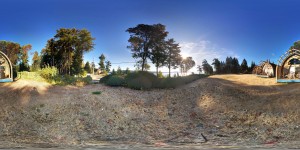
We’re going to start off with something much simpler — a standard photosphere. A photosphere is a single, non-stereoscopic spherical panorama image. The camera app on my Nexus 5 can create photospheres automatically, which is handy. Here’s one I took when I was on vacation on Salt Spring Island in British Columbia:
Photospheres, like many spherical videos, are stored using an equirectangular mapping. That’s just a fancy word for a Mercator projection, which is the format used for most maps of the world (the sort you may remember hanging on the wall of your classroom when you were a kid). All it really means is that if you put the lines of longitude and latitude on the image, they’ll form a grid where every cell is the same size. This is not the best way of storing a map (it really distorts the sizes of land masses on the earth, for example) but it works for what we’re going to be doing.
Setting up the scene
We need to create a sphere surrounding the virtual camera in our scene, and put the image on the inside of that sphere. We could model the sphere in something like Blender, but Unity already has a sphere primitive. That primitive even has vertex locations and texture coordinates that are perfect for an equirectangular projection. The only problem is that the sphere has its outside showing, and we need its inside showing. To do that, we’re going to use a shader.
Now, some people find shaders intimidating. However, in this case, we’re just going to use a regular off-the-shelf Unity shader and make two small changes to it.
The shader we’ll be using is the simplest one available, the “Unlit/Textured” shader. All we’re going to do is add a line to the shader to tell it to cull (i.e. ignore) the front faces, which by implication means to show the back faces, of each polygon it renders. That will cause the sphere to appear inside-out, and the texture that we apply to it will be on the inside. That’s almost what we want, except it will appear backwards since we’re looking at it from the opposite side (imagine writing something on a piece of glass, and then looking at it from the other side). To turn it around, we replace the X (i.e. U, the horizontal texture coordinate) with 1-X, so instead of ranging from zero to one it goes from one to zero. Both of those changes are commented in the shader source code at the end of this article. We’ll call our shader “InsideVisible”.
Once we have our shader, the next step is to create a sphere. Put it at the origin (0,0,0) and scale it up a bit (I arbitrarily scaled it by a factor of 10). Create a new material, and apply it to the sphere. Drag and drop your new shader into the material, then import the photosphere image and drop it onto that material.
And that’s it — assuming your Main Camera is at the origin, you should be able to select it and rotate it around to see the photosphere in the little camera preview window.
Now let’s add support for the Rift. Install the Oculus SDK, and drag in an OVRCameraController prefab (or an OVRCameraRig, if you’re on 0.43 or higher of the Oculus Unity SDK). Make sure it’s at the origin, and turn off positional tracking (since we only want to rotate our head, not move it relative to our sphere).

Hit Play and you should be able to look all around at your beautiful photosphere, reliving your vacation memories. Cool, eh?
Entering the third dimension
Now let’s take the next step — stereoscopic viewing. While we’re at it, let’s also move from a single static image to an actual video. Before we do that, note that you cannot create a stereoscopic image from two photospheres. I was going to write several very dense paragraphs explaining why that doesn’t work, but the folks over at eleVR have done a much better job of that than I would have, so I’ll just refer you to their article.
So, once you a have a spherical stereoscopic video (probably from a special camera rig), how do you display it?
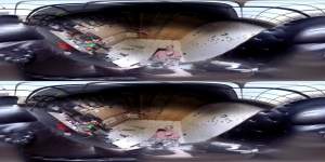
First, you need to understand the data you be working with. With stereoscopic video, you need to store two images for each frame (one for the left eye, one for the right). These images can be stored in a variety of layouts, including over-under, side-by-side, interlaced and so on. For this project, I’m only going to be supporting the over-under layout, though modifying the code to support side-by-side (SBS) stereo is straightforward once you understand how it works. In over-under layout, the pairs of frames are stacked one above the other with the left eye on top and the right eye on the bottom. If each image is (for example) 2048 by 1024, each video frame will be 2048 by 2048, and will look something like this:
A second sphere
Because we have two eyes, we need to have two spheres instead of just one. The left eye image will be on one sphere, the right eye image will be on the other.
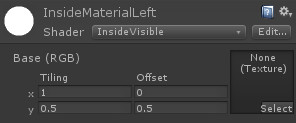
Start by duplicating your existing sphere. Rename one copy to “left” and the other to “right” to avoid confusion. Also rename your material to “left” and create a new one called “right”, using the same shader, and drop it onto the “right” sphere. At this point, if you were to drag the image above onto both materials, both spheres would show the complete image. What we want to do is have the left sphere show the upper half of the image and the right sphere show the lower half of the image. To do that, we’re going to play with the texture coordinates.
Unity materials have “tiling” and “offset” fields. The “tiling” field says how many times the texture should be repeated in the corresponding direction (X or Y) across the surface of the object. For example, a tiling Y value of 7 would cause the texture to be repeated (i.e. tiled) seven times along the vertical axis. Because each sphere is going to have half the texture (either the upper half or the lower half), you want to set the Y tiling value to 0.5. In other words, the texture will repeat not once, but only half a time in the vertical direction. If you do that for both the left and right materials, both spheres will only display the upper half of the texture. For the left-eye part of the texture, you need to offset that by half, so set the Y offset for the left material to 0.5.
Cameras and Layers
At this point, if you were to take a single frame of the over-under video and apply it as a texture to both spheres, the left sphere would have the left-eye image and the right sphere would have the right-eye image. However, by default, both left and right cameras show both spheres. We want to separate them, so each camera sees only one sphere.
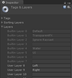
To do that, we’re going to use layers. Don’t worry if you’ve never used layers before — they’re easy. Go to the Layers menu at the top right of the Unity Inspector panel, and go to Add Layer. If you haven’t created any layers before, you’ll be using layers 8 and 9. Just fill in the names “left” and “right”.
Now go to your two spheres, and make sure the left sphere is on the left layer and the right sphere is on the right layer. Finally, go to your left camera and make sure it only renders the “left” layer (click on the culling mask, select “Nothing” from the dropdown, then “Left”). Do the same for the right camera (selecting “right”, of course).
And that’s it — all the hard setup work is done. Save your project.
Let’s talk about your orientation…
Sometimes the video was shot with the camera oriented in an unusual way, so that when you’re looking forward with your head level in the real world, you’re looking in some random direction in the virtual world. This is easy to correct for — just select both the left and right spheres and use the Unity rotation tool to orient them however you like. Be sure you rotate both spheres together, since you don’t want them mis-aligned. Also be careful not to translate the spheres (in other words, keep them at the origin).
Bring on the video!
The simplest way to get the video playing is to simply drag it into your project (note that importing will take a very, very long time) and then drag-and-drop it onto both materials. Unlike with audio clips, Unity doesn’t automatically start playing videos when it starts up. You’ll need to do that in software, using a little script that looks like this:
using UnityEngine;
using System.Collections;

public class VideoViewer : MonoBehaviour
{
	public GameObject leftSphere, rightSphere;

	void Start ()
	{
		((MovieTexture)leftSphere.renderer.material.mainTexture).Play ();
		((MovieTexture)rightSphere.renderer.material.mainTexture).Play ();
	}

}
Just create an empty GameObject and drop the script onto it. Drag the left sphere into the leftSphere field, and the right sphere into the rightSphere field.
If you want to add audio, it’s pretty easy. Just add an audio source component to your GameObject (the one that has the script). Drag the video clip onto the audio source component. By default, Unity will play the audio when the scene loads. If you want more control, turn off “Play on awake” and add the line “audio.Play();” to your script.
All this works fine, with the video coming into Unity as a MovieTexture. However, there are four problems:
- MovieTexture requires Unity Pro, which not everyone has
- MovieTexture doesn’t work on mobile devices, even with the Pro version of Unity
- Not all videos work well (some just give you a black material)
- Even if they play back properly, they may kill your framerate
If you’re using Unity Pro, and you’re only targeting desktop systems (Windows or Mac), and you have a fast enough computer to simultaneously handle the video decoding and the rendering while keeping up a decent framerate, then MovieTexture is a good way to go. If you’re getting a black material, try transcoding your video using something like ffmpeg:
ffmpeg -i "your_original_file.mp4" -s 2048x2048 -q:v 5 "your_project_folder/Assets/your_new_file.ogg"
Notice the .ogg extension on the output file. When Unity imports a video clip, it converts it to Ogg Theora format. You can speed up the importing quite a bit if you convert it to that format during transcoding. You may also save one generation of loss in the conversion, which will give you better quality. Speaking of quality, the “-q:v” means “quality scale for video”, which is followed by a value from zero to ten. The default is way too low, which will give you very noticeable banding and other artifacts. I use 5 as a reasonable compromise between speed and quality. I also resize the video at the same time, and make it a power of two (which Unity will enforce anyway during import, so may as well get it out of the way now and save some cycles during loading). The original video I used in my testing was 2300×2300, and I suspect Unity internally rounds up to the next power of two rather than the closest. That would make it 4096×4096, which is a lot of data to move around.
An alternative: split the video into frames
If you don’t have Unity Pro, or you don’t have a fast computer, or you’re targeting mobile, the MovieTexture solution won’t work. The alternative is to convert the video to a series of separate jpeg files and play them back at runtime. To do this, we again turn to ffmpeg:
ffmpeg -i "your_original_file.mp4" -s 2048x2048 -q:v 5 "your_project_folder/Assets/Resources/frame%4d.jpg"
This will put a bunch of jpeg files into your Resources folder (which you will need to create first), replacing the “%4d” with “0001” for the first frame, “0002” for the second frame and so on. Each frame of the original video file will produce a jpeg, so there will be quite a few of them. Wait until Unity finishes importing them all (might be a good time to grab some lunch).
We’ll remove the VideoViewer script from our empty GameObject and replace it with one that looks like this:
using UnityEngine;
using System.Collections;

public class JpegViewer : MonoBehaviour
{
	public GameObject leftSphere, rightSphere;  // the two spheres
	public int numberOfFrames = 0;
	public float frameRate = 30;

	private Texture2D[] frames;

	void Start ()
	{
		// load the frames
		frames = new Texture2D[numberOfFrames];
		for (int i = 0; i < numberOfFrames; ++i)
 			frames[i] = (Texture2D)Resources.Load(string.Format("frame{0:d4}", i + 1));
 	}

 	void Update () 	{
 		int currentFrame = (int)(Time.time * frameRate);
 		if (currentFrame >= frames.Length)
			currentFrame = frames.Length - 1;
		leftSphere.renderer.material.mainTexture = rightSphere.renderer.material.mainTexture = frames[currentFrame];
	}
}
As with our previous script, you’ll need to drag the left sphere into the leftSphere field of this script component, and the right sphere into the rightSphere field. Also make sure that the number of frames matches the number you actually generated, and the frame rate matches that of the original video (usually 30).
This script loads in video frames from the Resources folder and stores them in an array. On every (rendering) frame, it uses the current time multiplied by the frame rate to compute which (video) frame to display on the textures. Again, we’re putting the same texture into both materials and using the Y tiling and offset values to separate them.
And that’s it.
Adding audio
If you want to add sound, you can extract the audio from the original video clip like this:
ffmpeg -i "your_original_file.mp4" -vn "your_project_folder/Assets/your_audio.wav"
(the “-vn” means “skip the video”). Go into the import settings and turn off “3d sound” on the audio clip. Then add an Audio Source component to the GameObject that holds your script, drag the audio clip onto that component, and turn off “Play on awake” (to avoid having the audio start before the frames are loaded). Modify the script’s Update() method to look like this:
	void Update ()
	{
		if (!audio.isPlaying)
			audio.Play ();
		int currentFrame = (int)(Time.time * frameRate);
		if (currentFrame >= frames.Length) {
			currentFrame = frames.Length - 1;
			audio.Stop ();
		}
		leftSphere.renderer.material.mainTexture = rightSphere.renderer.material.mainTexture = frames[currentFrame];
	}
Lo and behold… nice, fast stereoscopic spherical video playing back in Unity, with audio.
Building for Android Using the DIVE SDK
One of the great things about the individual-frame approach is that you can use it on mobile devices. I’m going to use the Dive library for tracking. Once you have it installed, just delete the OVRCameraController, drag the Dive_camera prefab into the scene, put it at the origin, and set the cameras to render the appropriate layers (left and right). That’s literally all you have to do!
There are two things to note. The first is that the VideoViewer script we wrote won’t compile in the Android build, so either delete it or surround the Start() method with an “#if (UNITY_PRO && (UNITY_EDITOR || UNITY_STANDALONE) ) … #endif”. The other is that the mere presence of the video clip in your assets is enough to cause the Android build to fail, so you’ll have to delete that file as well. Also, when switching between platforms, all the assets get re-imported. If you have thousands of jpegs, that will take a really long time.
Also note that mobile devices have very limited amounts of memory. For testing, I’ve kept the videos to 15 seconds or less, and that works fine. Any more than that, and we’d have to get clever about the loading and unloading of the images so that only a few seconds’ worth are stored in memory at any given time.
Building for Android Using the Google Cardboard SDK
Supporting the Google Cardboard SDK is very similar. However, their SDK is not designed to support separate culling masks for each of the cameras. It’s easy to change this — just edit CardboardEye.cs and add a variable for the culling mask:
public int cullingMask;
Then find the line that copies the parameters from the main camera to the eye-specific camera, and add a line right after it to set the culling mask:
camera.CopyFrom (controller.GetComponent<Camera> ());
camera.cullingMask = cullingMask; // add this
Then in the Inspector, set the cullingMask values on each CardboardEye. The value you set will be a bitmask, equivalent to 1 << LayerNumber. If your left layer is number 8, then the value for the cullingMask for the left CardboardEye script will be 1 << 8, or 256. If your right layer is number 9, then the value of the culling mask for the right eye will be 1 << 9, or 512. If you want other layers visible as well (e.g. the UI layer) just add the correct value (32 in the case of the UI layer).
What about the Gear VR?
I would expect that if you install the Oculus SDK for the Gear VR, it should all just work fine. I don’t actually have a Gear VR myself ($826 for the Note 4 plus $200 for the Gear VR itself = not happening, unfortunately), but if anyone does try it out I’d love to know if it works.
Finding the Code
I’ve created two Unity packages containing the code from this article, one for the Oculus version and one for the Android version (using the Google Cardboard SDK). Be sure to import them into empty projects, so they don’t overwrite anything. Also be sure to check out the README files.
Next steps…
There are lots of other things you can do. Right now the video stops playing at the end, but you could easily make it loop. You could also trigger it, say from the user hitting a key or clicking a mouse button. You could get into spatial positioning of the audio. You could try adding 3D objects to the scene. You may want to add a “Loading” message, since it takes a while for things to load in.
Have fun, and let me know what you come up with!
Oh, before I forget, here’s that shader I mentioned earlier:
// Based on Unlit shader, but culls the front faces instead of the back

Shader "InsideVisible" {
Properties {
	_MainTex ("Base (RGB)", 2D) = "white" {}
}

SubShader {
	Tags { "RenderType"="Opaque" }
	Cull front    // ADDED BY BERNIE, TO FLIP THE SURFACES
	LOD 100

	Pass {
		CGPROGRAM
			#pragma vertex vert
			#pragma fragment frag

			#include "UnityCG.cginc"

			struct appdata_t {
				float4 vertex : POSITION;
				float2 texcoord : TEXCOORD0;
			};

			struct v2f {
				float4 vertex : SV_POSITION;
				half2 texcoord : TEXCOORD0;
			};

			sampler2D _MainTex;
			float4 _MainTex_ST;

			v2f vert (appdata_t v)
			{
				v2f o;
				o.vertex = mul(UNITY_MATRIX_MVP, v.vertex);
				// ADDED BY BERNIE:
				v.texcoord.x = 1 - v.texcoord.x;
				o.texcoord = TRANSFORM_TEX(v.texcoord, _MainTex);
				return o;
			}

			fixed4 frag (v2f i) : SV_Target
			{
				fixed4 col = tex2D(_MainTex, i.texcoord);
				return col;
			}
		ENDCG
	}
}

}


Pingback: Pre-rendered spherical stereoscopic panoramas | Bernie Roehl
Pingback: Full 360 stereoscopic video playback in Unity | VRNW Wiki
Pingback: How to replicate the Google Cardboard Photosphere App - DexPage