Is 360 Video “VR”?

No.

I was tempted to have that simple “No” be the entire blog post, but I think it’s important to understand the reasons behind it.

First off, let me say that 360 video is awesome. In spite of all the limitations I’ve discussed elsewhere, 360 is a very powerful medium and I’ve seen some truly compelling content that has affected me on a deep, emotional level.

However, I think that calling it “VR” is doing a disservice to both VR and 360 video, and that 360 video will suffer from the comparison.

I’ve given countless VR demos to a wide variety of people over a long period of time. Depending on what hardware I’m using, I’ll start them off with something like The Lab (on the HTC Vive) or First Contact (on the Oculus Rift). One of the things people seem to love the most is photogrammetry — reconstructions of the real world from a large number of photos. There are some excellent examples of this in The Lab, for example, including the first thing people see there which is “Vesper’s Peak”.

People will put on the headset and immediately go “wow!” — they look at the mountain, and it’s much sharper and clearer and more realistic than they expected it to be. Then I tell them to turn their head and look around, and I get a second “wow!”. Then I tell them to walk around, then crouch down and look closely at the ground, and I get a third “wow!”. Then the robot dog comes along and I tell them to reach out and pet it, and throw a stick for it to fetch, and they’re absolutely enthralled.

Then I’ll show them some 360 video. The first thing they do is ask me how to adjust the focus. I show them, but I know that it’s not going to do any good. The problem is not with the focus, the problem is with the resolution of the video. Most content creators are still shooting and editing at 4K resolution, which of course is way too low for VR. The person trying the demo also notices the stitching lines, and the issues at the zenith and nadir, and the fact that the image is flat (or, if it’s stereoscopic, that it’s not stereoscopic when they look up or down or tilt their head). And they can’t move around. And there’s nothing they can interact with. After a minute or less, they ask to go back to the previous demo so they can play with the dog some more.

And that’s why it’s important to distinguish 360 video from VR. Aside from the fact that they’re both viewed through a headset, they’re completely different. Keeping them separate provides a way of setting peoples’ expectations of what each medium is capable of.

So what are the strengths of 360 video? The most important thing it offers is that it’s directly captured from the real world. It’s not CGI, it’s not heavily post-processed, it’s not the result of clever edits and special effects… it’s the real thing, shot exactly as if you were there. That’s why it’s been such a perfect fit for documentaries, where the simple reality of what you’re seeing is much more important than the visual quality. It’s also great for capturing personal experiences, whether it’s a first-person view of a sporting event, or a once-in-a-lifetime family reunion, or an intimate encounter, or traveling to some faraway place. Those are the sorts of things that 360 video will always do better than VR, and those things all have real value.

Calling 360 video “VR” is not only misleading, it hurts both media. People whose only exposure to “VR” is 360 video won’t get to see the full potential of the medium, which hurts the VR industry. And people who have seen actual VR will start to look at 360 video as an inferior alternative, the “cheap” kind of VR that’s never as sharp and crisp and interactive as the real thing.

By giving 360 video its own identity, distinct from VR, we can make it a first-class citizen in the world of immersive media. People will learn to recognize its particular strengths and weaknesses, rather than see it as the poor cousin of actual VR.


About ARKit and ARCore

There’s a lot of excitement about the back-to-back releases of ARKit (from Apple) and ARCore (from Google).

They’re very similar, since they’re both derived from the same original source code, and they both provide the same basic information to an app — the camera’s position in the physical world, a sparse point cloud, and a set of bounded planes.

That’s sufficient to put virtual objects and animated characters on tabletops, or on the floor, or even sticking out from a wall. Very cool… but also very limited. Here’s a list of the shortcomings of the toolkits:

  1. No occlusion. Since there’s no depth camera, neither ARKit nor ARCore can provide a true 3D model of the space you’re in. That means that (unless a developer is very, very clever) the 3D models that are displayed will always be rendered in front of the real-world scene. You might have a dancing bear on the tabletop, but it won’t be walking around behind the salt and pepper shakers because those objects don’t exist in the app.
  2. No stereo depth. Since ARKit and ARCore run only on specific phones, and not in any kind of headset with separate displays for each eye, the images that are added to the world will always be flat. They won’t have the depth or realism that you would get from stereoscopic 3D.
  3. No connection to the real world. All the toolkits can tell the app is where the points and planes are in the user’s immediate vicinity. There’s no way of connecting that to specific objects in the real world, so there won’t be any augmented street signs or new facades on buildings or anything like that. There are ways of solving this (e.g. fiducial markers), but neither toolkit supports those. Theoretically you might be able to send the point data and GPS coordinates to the cloud to figure out what the user is looking at, but at the moment no such capability exists.
  4. Without any connection to specific points in the real world, multi-user AR experiences are difficult or impossible to implement. So everything will be single-user only.
  5. Holding up your cellphone all the time is really uncomfortable, and the novelty will wear off as soon as your arm gets tired.

Given those limitations, I suspect developers will have a hard time coming up with actual applications for ARKit and ARCore beyond some cool demos of scary clowns and dancing mice.

Devices like the Hololens and the Meta 2 glasses solve some of the problems listed above, but they’re extremely bulky and insanely expensive.

Impressive though ARKit and ARCore are as technical achievements, they’re only a small step in bringing AR to the consumer market.

AR is definitely coming, but it’s not here yet.


Why Most “Cinematic VR” Looks So Bad

This is one of those questions that comes up so often that I’ve decided to do a blog post about it.

People will often watch 360 videos, either monoscopic or stereoscopic, and be disappointed in the quality. Regardless of who created the content, people frequently seem surprised at the poor resolution — even when the video is 4K. They often (mistakenly) think it’s a limitation of the VR headset, which it’s not.

In fact, people will sometimes compare content created using a realtime game engine such as Unity (e.g. The Lab on HTC Vive or Dreamdeck on the Oculus Rift) to recorded 360 degree video, and wonder why the 360 video looks so much worse than the game engine content.

I’m going to try to give a simple explanation of where the problem is.

Let’s start with some math. Most VR headsets have a field of view of 100 degrees. That’s measured diagonally, same as with television sets. If you buy a 60 inch TV, that’s 60 inches measured diagonally (corner to corner). Same with VR headsets — they’re 100 degrees diagonal, with an approximately square aspect ratio for each eye, so you have approximately 72 degrees horizontal by 72 degrees vertical. In other words, one fifth of a full panorama (360 divided by 72). That’s an important number, so keep it in mind.

So let’s say you shoot a 360 stereoscopic video and render it out at 4K resolution. First of all, “4K” is not really 4K. Most people use “4K” to refer to UHD, which is actually 3840 pixels horizontally by 2160 pixels vertically. Assuming the image is stored in SBS format (Side By Side — left eye image in the left half of the screen, right eye image in the right half) then you’re only left with 1920 pixels horizontally per eye.

Now, you may be thinking “No problem — that’s still full HD resolution for each eye. Should be plenty!”.

However, here’s the thing – – those 1920 pixels are spread out over the full 360 degrees. Since (as described above) you can only see 1/5 of those 360 degrees at any given time, you’re getting 1920/5 or 384 pixels horizontally. It’s a bit better in the vertical direction — you’re getting 72 degrees out of 180, or about 1/2.5. so you’re seeing 864 pixels vertically.

A modern VR headset has way higher resolution than that. The Gear VR gives you 1280 by 1440 pixels per eye, vs 384 by 864, so the headset is capable of displaying nearly six times as many pixels as are actually in your video. To put it another way, each pixel in your video is stretched out to cover approximately six pixels on the screen. It’ll either be very pixelated or really blurry, depending on how the video was processed.

And of course, if you’re streaming, you also have to compress the video down to a bitrate that can be sent over the internet. That compression further reduces the visual quality.

So 4K is just barely adequate. For current VR headsets, 8K is much better. However, if you’re using mobile VR, then you’re limited by the available codecs (which may not support 8K, since it exceeds the resolution of the phone’s screen).

All of this does not mean you shouldn’t keep making 360 videos!  Just be aware of the limitations of the medium, use the highest resolution your target platform supports, and manage your clients’ expectations accordingly.


Limits of Cinematic VR

There’s been a lot of interest lately in “cinematic VR”, and a lot of confusion about exactly how it works. Since I’ve had to answer the same questions multiple times, I thought I would put all the answers together into a blog post so I can refer people here rather than explaining it over and over.  🙂

There are two basic types of VR experiences.

The first type uses realtime, interactive 3D graphics to display a virtual world. The scene is represented by a large number of small triangles (polygons) and is typically displayed using a game engine such as Unity or Unreal. In this type of VR, you have complete freedom to move around, look wherever you like, and experience the entire world in full stereoscopic 3D. The disadvantage is that because the entire scene has to be rendered at anywhere from 60 to 120 frames per second, some sacrifices have to be made in terms of richness and detail.

The second type of VR experience uses either real-world video footage that’s been captured using a special camera rig, or pre-rendered computer graphics that typically have a lot more detail than could be rendered using a realtime game engine. It’s this second type that is the focus of this blog post.

The term “cinematic VR” is often used to describe this type of VR, since the technology is very similar to that of film. A set of cameras (real or virtual) is used to produce a linear experience that may or may not be viewed stereoscopically. The visual quality is generally much better than that of realtime VR, but the tradeoff is that the user has very limited (if any) freedom to interact with the experience.

Basic Technology

In order to better understand the limitations of cinematic VR, let’s take a look at how it works. The simplest form of cinematic VR is a simple 360-degree spherical monoscopic video. The user is basically surrounded by a virtual sphere on which is projected a video. They can look all around (360 degrees horizontal) and all the way up and down (180 degrees vertical). There are many cameras that can be used to create this sort of video, including Bublcam, the various 360heroes rigs, and more. For content distribution, there are a number of websites that aim to be the “Youtube of VR video”, and of course Youtube itself has recently added support for these kind of 360 degree monoscopic videos.

However, this approach has a huge limitation. With a monoscopic camera, what the user is seeing is still a flat image — there’s no depth to it. That’s fine if everything in the scene is far away, such as when the user is standing in the Grand Canyon or hang gliding over the Azores. However, as soon as you move to an indoor scene where objects are closer to the camera, the illusion is broken. It’s immediately clear that you’re just looking at a projection onto a sphere, not actually standing in a virtual environment.

That brings us to the next “level” of cinematic VR — stereoscopic viewing. Most people are somewhat familiar with how ordinary stereograms work — the idea is that you  present a slightly different image to each eye, so that the brain can use the disparities between the images (parallax) to get a sense of depth. That’s the principle behind everything from a Viewmaster to a 3D movie.

Creating stereoscopic video from a single point of view is pretty straightforward — two cameras, side by side, give you a pair of images that you can display to the user to recreate the scene in three dimensions. The challenge is to combine this stereoscopic viewing with a full 360 x 180 spherical view. That brings us to…

Issue #1 — You need a special camera rig

A lot of people mistakenly assume that it should be as simple as taking two monoscopic spherical cameras (such as the Bublcam) and placing them side by side. That doesn’t work at all, and when you think about it for a bit you can see why. Each of the two cameras is capturing a spherical panorama from the location of the corresponding eye. However, when you look in different directions in the real world, your eyes don’t swivel through 360 degrees in their sockets — instead, they rotate around a central point (the top of your neck). That makes a huge difference.

To understand the difference, imagine that you have captured a 360 degree spherical image from each of two cameras separated by approximately the same distance as your eyes. When you’re looking straight ahead, everything is great — you see perfect stereo, as captured by the cameras. However, when you try looking over your right shoulder, the view you see from the two cameras no longer gives you any parallax — the cameras are aligned with each other, and are looking in the exact same direction. Any sense of stereo depth has completely disappeared.

Things get even worse when you rotate past 90 degrees. The sphere for the right eye is now showing the left-eye perspective, and the sphere for the left eye is now showing the right-eye perspective. Your brain has no idea what to do with this, and all you can do is close one eye and view the scene monoscopically. You can avoid this reversal by sticking to an upright hemisphere, 180 horizontal by 180 vertical, instead of trying to do a full 360 degrees around. Even so, you’ll only have stereo depth when looking straight ahead, and it will diminish to zero as you look towards the sides, top or bottom of the hemisphere. If that’s acceptable, you can simply use a pair of cameras with fisheye lenses to capture the scene.

The right way to do it for a still image is to rotate a pair of conventional cameras around a central point, taking a series of shots, and then stitch them together for each eye separately. Experience has shown that 30 to 40 rotation steps are enough to produce good results.

However, that obviously doesn’t work for video, which is why people are developing complicated rigs (such as IZugar, 360Heroes 3DH3PRO12H, Jaunt, Samsung’s Project Beyond and others). These rigs have multiple cameras arranged in a circle, each camera equipped with a wide-angle lens. The cameras can be grouped in pairs, and images from the left-eye cameras are stitched together separately from the images from the right-eye cameras. Because you typically only have half a dozen pairs of cameras (compared with the 30 to 40 rotation steps for the still-image case), there’ll be some quite noticeable stitching artifacts (seams).

Issue #2 — Fixed IPD

The distance between your eyes, often referred to as the Inter-Pupilary Distance or IPD, varies quite a bit from one person to another. However, in any stereoscopic camera rig the cameras will be a fixed distance apart. That means the world will look perfect for some people (the ones whose IPD is a close match for the camera spacing) but will look wrong for most others. There’s nothing to be done about this in software, since it’s purely the result of a mismatch between two physical distances (the spacing of the cameras and the IPD of the viewer).

Issue #3 — You can’t tilt your head

In this case, by “tilt your head”,  I mean tip your head over onto your left or right shoulder (what more accurately would be called “rolling” your head). You can look all around you, and you can look up and down (with the caveat that you lose stereo depth, as described above), but if you tip your head you lose the illusion completely. Again, it’s easy to see why — the cameras were side by side when the footage was shot, not at an angle, and if your eyes are at an angle it won’t look right. In fact, cinematic VR playback systems usually ignore rolling altogether, and only pay attention to pitch and yaw (i.e. looking up and down and all around).

And speaking of ignoring inputs…

Issue #4 — You can’t move your head

This is perhaps the biggest limitation of cinematic VR. Since the footage was only shot from one specific location, it can only be viewed from one location. To understand this, imagine that the camera rig was set up in an office, facing an open door leading to the hallway. Now imagine that in the hall, just a bit to the left of the doorway, is a coat rack. Also imagine that just a bit to the right of the doorway is a chair.

If the camera rig is facing the door, it will see the hallway and neither the coat rack nor the chair will be visible. If you were actually sitting where the camera was positioned, you could shift over a bit to your right to see the coat rack, or a bit to your left to see the chair. However, when viewing the scene in VR, that doesn’t work — no matter how much you move your head left or right, you’ll never see the coat rack or the chair, since they were never visible to the camera. Cameras can’t see around corners, and no amount of clever software will let you see something that wasn’t recorded!

If you try to move your head in a cinematic VR experience, even a little bit, all that will happen is that the image will be distorted. The further your head moves away from the location of the camera, the more distortion there’ll be. That’s why cinematic VR players ignore positional input, since there’s no way to make use of it.

The Future

Are there ways around these limitations? Not using current approaches, no. However, it’s possible to get around all of these problems using lightfields — but that’s a technology that won’t be available for a while, and it will be a topic for another blog post.


ImmerView

I’ve taken some of the ideas I’ve talked about in my blog, and used them to create an app for Google Cardboard and other similar frames (Durovis Dive, VR One, Homido and many, many others). I’ll be porting to the Oculus Rift shortly.

It’s called ImmerView, and it’s basically a modern-day Viewmaster that lets you look at a series of 3D slides. The big advantage over Viewmaster is that you can look all around you.

It’s free, and it has a small but growing library of content. You can find the app on the Play Store.

Hope you enjoy it!

Pre-rendered spherical stereoscopic panoramas

In a previous article I described how to display full-spherical stereoscopic images and videos in Unity. In this article I’m going to start looking at how to create that content.

One approach (described in detail on the excellent eleVR site) uses a rig consisting of multiple cameras to capture stereoscopic image pairs which are then stitched together in software to create a pair of spherical images, one for the left eye and one for the right. The results can be quite good, but there are two fundamental problems with this approach — one technical, one practical.

The technical problem has to do with the need for the cameras to have overlapping fields of view in order for the stitching software to work. That inevitably means that there’s a minimum distance between the center of the camera rig and the objects in the scene. Anything closer than that won’t be visible, and certainly won’t be seen stereoscopically. That distance is typically about four or five feet, which is unfortunate since that’s the distance range in which stereoscopic depth perception is the strongest.

The practical problem is that cameras are expensive. I have yet to see a spherical stereoscopic rig with fewer than six cameras with very wide-angle lenses, so you’re looking at several thousand dollars for a full rig. That’s a lot of money, certainly for a hobbyist, and definitely for me.

Fortunately, capturing images from the real world is not the only way of generating spherical stereoscopic content. You can use CGI to generate the images entirely in software, so there are no hardware costs and no limitations on how close objects can get to your (virtual) camera. I suspect that most of the immersive film style content that will be available in the next few years will come from large animation houses like Pixar rather than from people shooting actual video footage.

How it Works

The basic idea is to create the software equivalent of a stereoscopic camera rig, with a pair of virtual cameras separated by some distance (typically, something close to a normal inter-pupillary distance (IPD) of 60 millimeters or 0.06 meters). For each camera, we render a series of 360 narrow vertical strips, each covering 1 degree of longitude and 180 degrees of latitude. We rotate the cameras about their common pivot point by 1 degree for each strip. The virtual cameras use an equirectangular projection, so each vertical strip occupies the same width across our final output image.

Once we have all these image strips, we then join them together to form a pair of images (left eye and right eye). Finally, we combine the two images into one frame using an over-under layout, and we’re done.

If  you’re interested in a more detailed description of all this, you should definitely take a look at this paper that Paul Bourke wrote over a decade ago. It describes it all really well, with lots of pictures.  🙂

The question is, what software should we use to do the rendering? There are several options, but most of them cost more than the stereoscopic camera rig would! If you have a budget for your project,  you could use Maya or 3D Studio Max along with the free Domemaster3D shader, which appears to do exactly what you need.

However, we want to be able to do all this using entirely free software. There’s Blender, of course, but it does not seem to know how to render a spherical image (at least, not as of January 2015 — hopefully that will change).

For a while, I scratched my head. There is a lot of commercial rendering software that can do it, but nothing free and/or open source. Until I remembered an old friend…

Enter POV-RAY

Back before I became involved in VR (a long, long time ago), I was interested in pre-rendered computer graphics. One of the cleverest ways of creating beautiful images was a technique called raytracing. A raytracer works by firing an imaginary beam from your virtual camera position through a particular pixel in the output image, and seeing what it hits in the scene. For every point it hits, you generate additional rays representing reflections and refractions and continue tracing those paths until you reach a light source. You then repeat that for every pixel.

Back in the day, there were lots of raytracers out there. One reason for that is that they’re easy and fun to write, and a lot of people create them for school assignments. I wrote one myself in C, and it was only a few pages long. Of all the raytracers I tried (and I did a ton of side-by-side comparisons), there was one that stood out above all the others — the Persistence Of Vision Raytracer, or POV-RAY.

Flash forward quite a few years, to the present. When I started looking for free software-based renderers, one of the first ones I came across was my childhood friend POV-RAY. It brought back some nice memories. Out of curiosity, I looked for some of his contemporaries. Sadly, they had all passed away leaving nothing but 404 errors. Fortunately, POV-RAY is just what I needed.

POV-RAY, like most raytracers, uses a scene description language. You create a text file containing a description of all the objects in the scene, all the light sources, and the position and properties of your virtual camera. Then you run the raytracer on that file, and a little while later you get a beautiful image of your scene. Depending on the complexity of your scene, “a little while later” can vary quite a bit. A simple scene might render in a few minutes. A more complex one would have to run overnight. A really complex one… well, you may want to go on a nice vacation to someplace warm and sunny while it runs.

The good news is that raytracing parallelizes really well, so if you have (for example) 360 computers, you can render an entire image in the time it takes one computer to do a single strip. And modern raytracers can take advantage of multi-core CPUs (or better yet, GPUs) to speed things up dramatically.

Anyway, all we have to do is create our scene description and let POV-RAY do the rest.

Input Files

POV-RAY uses two different kinds of input files. The scene description itself is stored in a file that (typically) has a “.pov” extension. The information about the rendering process (resolution, output file format, things like that) are stored in a configuration file that has a “.ini” extension. Basically, the .pov file says what to render and the .ini file says how to render it.

We’re going to create two .ini files, one for the left eye and one for the right.

Here’s our left.ini file:

;; Configuration file for rendering the left-eye strips

Input_File_Name=left.pov
Output_File_Name=frames/left.tga
Output_to_File=on
Output_File_Type=T
Antialias=on
Antialias_Threshold=0.01
Display=off
Verbose=off

;; each frame is 10 pixels wide (so 3600 pixels in total)
;; by 1800 pixels high
Width=10
Height=1800

;; Make the panoramic in 1 degree slices
Initial_Frame=0
Final_Frame=359
Initial_Clock=0
Final_Clock=359

This says that the file to render is “left.pov” and the output files should be stored in the “frames” directory and should be named “left000.tga”, “left001.tga” and so on (TGA is an old-fashioned image file format). We render 360 frames in total, numbered zero through 359.

The right.ini file is very similar.  🙂

Now we need to set up the .pov files.  Rather than duplicate the scene description, we’ll store that in a separate file and use POV-RAY’s #include system to reference it (this should be familiar to anyone who programs in C). The left.pov file is tiny, and looks like this:

#version 3.7;
#declare EYE = 1;
#include "commonparameters.inc"
#include "stereopanoramic.inc"
#include "scene.pov"

The right.pov file is again quite similar. The EYE variable is set to 1 for the left eye and 2 for the right eye. We store a couple of rendering parameters that are common to both eyes in a separate file called commonparameters.inc and #include that here.We also #include a file called stereopanoramic.inc,  which sets up the virtual camera for stereoscopic rendering. That file originated on Paul Bourke’s site (see the link earlier in this article). I just made a couple of modifications to change the rendering from “perspective” to “spherical” and make the vertical field of view 180 degrees. Finally, we #include the actual scene description file called scene.pov. When creating scene.pov, remember to omit any camera since the camera gets set up in stereopanoramic.inc.

The commonparameters.inc file just has two lines:

#declare FOCAL = 0.75;
#declare CENTER = <0.0, 0.5, 0.0>;

These specify the focal length and the position of the camera (which you will want to change, to put it in an appropriate position in your scene).

With all this set up, we just run the POV-RAY renderer on each of the .ini files:

“c:\Program Files\POV-Ray\v3.7\bin\pvengine64.exe” /exit left

“c:\Program Files\POV-Ray\v3.7\bin\pvengine64.exe” /exit right

The result is two sets of image strips in the “frames” directory.

Image Magick

To assemble the strips, we again turn to an ancient but powerful piece of software called Image Magick. It can do all kinds of amazing image transformations, entirely from the command line. We’re only going to use one of its features, though — a program called “montage” that can assemble images together to form mosaics. For our purposes, this will do the trick:

montage frames\left*.tga -tile 360×1 -geometry +0+0 left.jpg

montage frames\right*.tga -tile 360×1 -geometry +0+0 right.jpg

The first command takes all the left*.tga files and assembles them into one, tiling them 360 horizontally and 1 vertically with no borders (+0+0) and converting the result into a jpeg file called “left.jpg”. The second command does the same for the right image strips.

One final command will combine the left and right images into our over-under format:

montage left.jpg right.jpg -tile 1×2 -geometry +0+0 output.jpg

If you want to do a side-by-side layout instead of over-under, just replace “1×2” with “2×1”.

The resulting output.jpg file is suitable for viewing using any stereoscopic image display software, including the Unity software I described in my previous article.

You may be wondering why I’m using command-line tools for all of this, rather than something with a graphical user interface. There is in fact a piece of software out there called Slitcher which does the joining up of the strips. I’ve never used it, but I’m sure it would work just as well as Image Magick. However, the big advantage of command-line tools is that you can use them in batch files which can run unattended for long periods of time. Both POV-RAY and Image Magick can also run on Linux systems, which is great if you want to set up  your own small render farm or buy time on a commercial one.

Anyway, that’s it for now. All of the code for this article, including a sample scene, can be found here.

Have fun!

Full 360 stereoscopic video playback in Unity

For a recent project, I needed to implement playback of stereoscopic spherical videos in Unity.

There are certainly people doing this already (e.g. Whirligig), but I needed to integrate the code with an existing application since we want to have 3D objects in the scene in addition to the stereoscopic video. Here’s how I went about it.

Starting simple

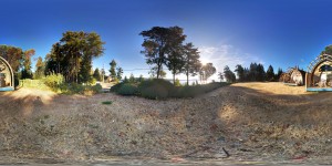
We’re going to start off with something much simpler — a standard photosphere. A photosphere is a single, non-stereoscopic spherical panorama image. The camera app on my Nexus 5 can create photospheres automatically, which is handy. Here’s one I took when I was on vacation on Salt Spring Island in British Columbia:

PANO_20140810_080527

Photospheres, like many spherical videos, are stored using an equirectangular mapping. That’s just a fancy word for a Mercator projection, which is the format used for most maps of the world (the sort you may remember hanging on the wall of your classroom when you were a kid). All it really means is that if you put the lines of longitude and latitude on the image, they’ll form a grid where every cell is the same size. This is not the best way of storing a map (it really distorts the sizes of land masses on the earth, for example) but it works for what we’re going to be doing.

Setting up the scene

We need to create a sphere surrounding the virtual camera in our scene, and put the image on the inside of that sphere. We could model the sphere in something like Blender, but Unity already has a sphere primitive. That primitive even has vertex locations and texture coordinates that are perfect for an equirectangular projection. The only problem is that the sphere has its outside showing, and we need its inside showing. To do that, we’re going to use a shader.

Now, some people find shaders intimidating. However, in this case, we’re just going to use a regular off-the-shelf Unity shader and make two small changes to it.

The shader we’ll be using is the simplest one available, the “Unlit/Textured” shader. All we’re going to do is add a line to the shader to tell it to cull (i.e. ignore) the front faces, which by implication means to show the back faces, of each polygon it renders. That will cause the sphere to appear inside-out, and the texture that we apply to it will be on the inside. That’s almost what we want, except it will appear backwards since we’re looking at it from the opposite side (imagine writing something on a piece of glass, and then looking at it from the other side). To turn it around, we replace the X (i.e. U, the horizontal texture coordinate) with 1-X, so instead of ranging from zero to one it goes from one to zero. Both of those changes are commented in the shader source code at the end of this article. We’ll call our shader “InsideVisible”.

Once we have our shader, the next step is to create a sphere. Put it at the origin (0,0,0) and scale it up a bit (I arbitrarily scaled it by a factor of 10). Create a new material, and apply it to the sphere. Drag and drop your new shader into the material, then import the photosphere image and drop it onto that material.

And that’s it — assuming your Main Camera is at the origin, you should be able to select it and rotate it around to see the photosphere in the little camera preview window.

Now let’s add support for the Rift. Install the Oculus SDK, and drag in an OVRCameraController prefab (or an OVRCameraRig, if you’re on 0.43 or higher of the Oculus Unity SDK). Make sure it’s at the origin, and turn off positional tracking (since we only want to rotate our head, not move it relative to our sphere).

s3d_ovr

Hit Play and you should be able to look all around at your beautiful photosphere, reliving your vacation memories. Cool, eh?

Entering the third dimension

Now let’s take the next step — stereoscopic viewing. While we’re at it, let’s also move from a single static image to an actual video. Before we do that, note that you cannot create a stereoscopic image from two photospheres. I was going to write several very dense paragraphs explaining why that doesn’t work, but the folks over at eleVR have done a much better job of that than I would have, so I’ll just refer you to their article.

So, once you a have a spherical stereoscopic video (probably from a special camera rig), how do you display it?

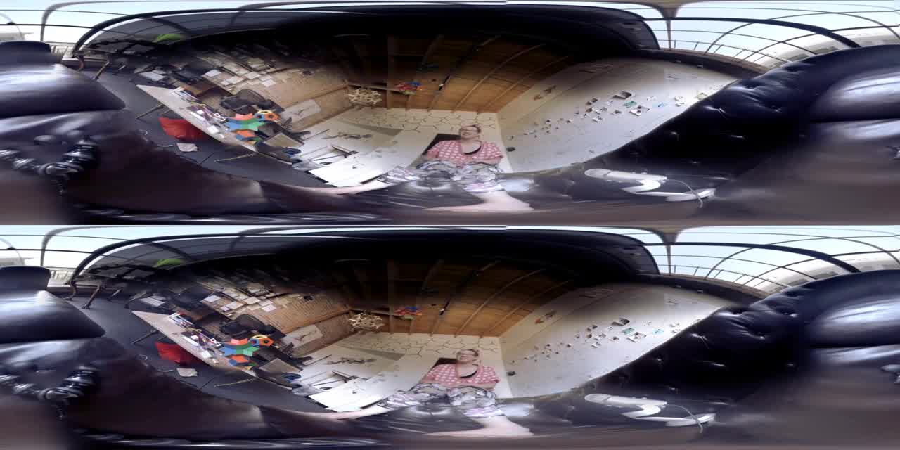
First, you need to understand the data you be working with. With stereoscopic video, you need to store two images for each frame (one for the left eye, one for the right). These images can be stored in a variety of layouts, including over-under, side-by-side, interlaced and so on. For this project, I’m only going to be supporting the over-under layout, though modifying the code to support side-by-side (SBS) stereo is straightforward once you understand how it works. In over-under layout, the pairs of frames are stacked one above the other with the left eye on top and the right eye on the bottom. If each image is (for example) 2048 by 1024, each video frame will be 2048 by 2048, and will look something like this:

frame2650

A second sphere

Because we have two eyes, we need to have two spheres instead of just one. The left eye image will be on one sphere, the right eye image will be on the other.

Start by duplicating your existing sphere. Rename one copy to “left” and the other to “right” to avoid confusion. Also rename your material to “left” and create a new one called “right”, using the same shader, and drop it onto the “right” sphere. At this point, if you were to drag the image above onto both materials, both spheres would show the complete image. What we want to do is have the left sphere show the upper half of the image and the right sphere show the lower half of the image. To do that, we’re going to play with the texture coordinates.

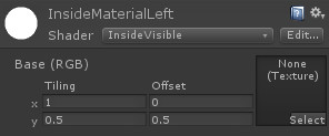
Unity materials have “tiling” and “offset” fields. The “tiling” field says how many times the texture should be repeated in the corresponding direction (X or Y) across the surface of the object. For example, a tiling Y value of 7 would cause the texture to be repeated (i.e. tiled) seven times along the vertical axis. Because each sphere is going to have half the texture (either the upper half or the lower half), you want to set the Y tiling value to 0.5. In other words, the texture will repeat not once, but only half a time in the vertical direction. If you do that for both the left and right materials, both spheres will only display the upper half of the texture. For the left-eye part of the texture, you need to offset that by half, so set the Y offset for the left material to 0.5.

s3d_texture

Cameras and Layers

At this point, if you were to take a single frame of the over-under video and apply it as a texture to both spheres, the left sphere would have the left-eye image and the right sphere would have the right-eye image. However, by default, both left and right cameras show both spheres. We want to separate them, so each camera sees only one sphere.

To do that, we’re going to use layers. Don’t worry if you’ve never used layers before — they’re easy. Go to the Layers menu at the top right of the Unity Inspector panel, and go to Add Layer. If you haven’t created any layers before, you’ll be using layers 8 and 9. Just fill in the names “left” and “right”.

s3d_layer

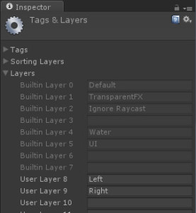
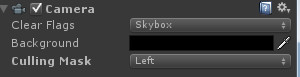
Now go to your two spheres, and make sure the left sphere is on the left layer and the right sphere is on the right layer. Finally, go to your left camera and make sure it only renders the “left” layer (click on the culling mask, select “Nothing” from the dropdown, then “Left”). Do the same for the right camera (selecting “right”, of course).

s3d_cam

And that’s it — all the hard setup work is done. Save your project.

Let’s talk about your orientation…

Sometimes the video was shot with the camera oriented in an unusual way, so that when you’re looking forward with your head level in the real world, you’re looking in some random direction in the virtual world. This is easy to correct for — just select both the left and right spheres and use the Unity rotation tool to orient them however you like. Be sure you rotate both spheres together, since you don’t want them mis-aligned. Also be careful not to translate the spheres (in other words, keep them at the origin).

Bring on the video!

The simplest way to get the video playing is to simply drag it into your project (note that importing will take a very, very long time) and then drag-and-drop it onto both materials. Unlike with audio clips, Unity doesn’t automatically start playing videos when it starts up. You’ll need to do that in software, using a little script that looks like this:

using UnityEngine;
using System.Collections;

public class VideoViewer : MonoBehaviour
{
	public GameObject leftSphere, rightSphere;

	void Start ()
	{
		((MovieTexture)leftSphere.renderer.material.mainTexture).Play ();
		((MovieTexture)rightSphere.renderer.material.mainTexture).Play ();
	}

}

Just create an empty GameObject and drop the script onto it. Drag the left sphere into the leftSphere field, and the right sphere into the rightSphere field.

If you want to add audio, it’s pretty easy. Just add an audio source component to your GameObject (the one that has the script). Drag the video clip onto the audio source component. By default, Unity will play the audio when the scene loads. If you want more control, turn off “Play on awake” and add the line “audio.Play();” to your script.

All this works fine, with the video coming into Unity as a MovieTexture. However, there are four problems:

  • MovieTexture requires Unity Pro, which not everyone has
  • MovieTexture doesn’t work on mobile devices, even with the Pro version of Unity
  • Not all videos work well (some just give you a black material)
  • Even if they play back properly, they may kill your framerate

If you’re using Unity Pro, and you’re only targeting desktop systems (Windows or Mac), and you have a fast enough computer to simultaneously handle the video decoding and the rendering while keeping up a decent framerate, then MovieTexture is a good way to go. If you’re getting a black material, try transcoding your video using something like ffmpeg:

ffmpeg -i "your_original_file.mp4" -s 2048x2048 -q:v 5 "your_project_folder/Assets/your_new_file.ogg"

Notice the .ogg extension on the output file. When Unity imports a video clip, it converts it to Ogg Theora format. You can speed up the importing quite a bit if you convert it to that format during transcoding. You may also save one generation of loss in the conversion, which will give you better quality. Speaking of quality, the “-q:v” means “quality scale for video”, which is followed by a value from zero to ten. The default is way too low, which will give you very noticeable banding and other artifacts. I use 5 as a reasonable compromise between speed and quality. I also resize the video at the same time, and make it a power of two (which Unity will enforce anyway during import, so may as well get it out of the way now and save some cycles during loading). The original video I used in my testing was 2300×2300, and I suspect Unity internally rounds up to the next power of two rather than the closest. That would make it 4096×4096, which is a lot of data to move around.

An alternative: split the video into frames

If you don’t have Unity Pro, or you don’t have a fast computer, or you’re targeting mobile, the MovieTexture solution won’t work. The alternative is to convert the video to a series of separate jpeg files and play them back at runtime. To do this, we again turn to ffmpeg:

ffmpeg -i "your_original_file.mp4" -s 2048x2048 -q:v 5 "your_project_folder/Assets/Resources/frame%4d.jpg"

This will put a bunch of jpeg files into your Resources folder (which you will need to create first), replacing the “%4d” with “0001” for the first frame, “0002” for the second frame and so on. Each frame of the original video file will produce a jpeg, so there will be quite a few of them. Wait until Unity finishes importing them all (might be a good time to grab some lunch).

We’ll remove the VideoViewer script from our empty GameObject and replace it with one that looks like this:

using UnityEngine;
using System.Collections;

public class JpegViewer : MonoBehaviour
{
	public GameObject leftSphere, rightSphere;  // the two spheres
	public int numberOfFrames = 0;
	public float frameRate = 30;

	private Texture2D[] frames;

	void Start ()
	{
		// load the frames
		frames = new Texture2D[numberOfFrames];
		for (int i = 0; i < numberOfFrames; ++i)
 			frames[i] = (Texture2D)Resources.Load(string.Format("frame{0:d4}", i + 1));
 	}

 	void Update () 	{
 		int currentFrame = (int)(Time.time * frameRate);
 		if (currentFrame >= frames.Length)
			currentFrame = frames.Length - 1;
		leftSphere.renderer.material.mainTexture = rightSphere.renderer.material.mainTexture = frames[currentFrame];
	}
}

As with our previous script, you’ll need to drag the left sphere into the leftSphere field of this script component, and the right sphere into the rightSphere field. Also make sure that the number of frames matches the number you actually generated, and the frame rate matches that of the original video (usually 30).

This script loads in video frames from the Resources folder and stores them in an array. On every (rendering) frame, it uses the current time multiplied by the frame rate to compute which (video) frame to display on the textures. Again, we’re putting the same texture into both materials and using the Y tiling and offset values to separate them.

And that’s it.

Adding audio

If you want to add sound, you can extract the audio from the original video clip like this:

ffmpeg -i "your_original_file.mp4" -vn "your_project_folder/Assets/your_audio.wav"

(the “-vn” means “skip the video”). Go into the import settings and turn off “3d sound” on the audio clip. Then add an Audio Source component to the GameObject that holds your script, drag the audio clip onto that component, and turn off “Play on awake” (to avoid having the audio start before the frames are loaded). Modify the script’s Update() method to look like this:

	void Update ()
	{
		if (!audio.isPlaying)
			audio.Play ();
		int currentFrame = (int)(Time.time * frameRate);
		if (currentFrame >= frames.Length) {
			currentFrame = frames.Length - 1;
			audio.Stop ();
		}
		leftSphere.renderer.material.mainTexture = rightSphere.renderer.material.mainTexture = frames[currentFrame];
	}

Lo and behold… nice, fast stereoscopic spherical video playing back in Unity, with audio.

Building for Android Using the DIVE SDK

One of the great things about the individual-frame approach is that you can use it on mobile devices. I’m going to use the Dive library for tracking. Once you have it installed, just delete the OVRCameraController, drag the Dive_camera prefab into the scene, put it at the origin, and set the cameras to render the appropriate layers (left and right). That’s literally all you have to do!

There are two things to note. The first is that the VideoViewer script we wrote won’t compile in the Android build, so either delete it or surround the Start() method with an “#if (UNITY_PRO && (UNITY_EDITOR || UNITY_STANDALONE) ) … #endif”. The other is that the mere presence of the video clip in your assets is enough to cause the Android build to fail, so you’ll have to delete that file as well. Also, when switching between platforms, all the assets get re-imported. If you have thousands of jpegs, that will take a really long time.

Also note that mobile devices have very limited amounts of memory. For testing, I’ve kept the videos to 15 seconds or less, and that works fine. Any more than that, and we’d have to get clever about the loading and unloading of the images so that only a few seconds’ worth are stored in memory at any given time.

Building for Android Using the Google Cardboard SDK

Supporting the Google Cardboard SDK is very similar. However, their SDK is not designed to support separate culling masks for each of the cameras. It’s easy to change this — just edit CardboardEye.cs and add a variable for the culling mask:

public int cullingMask;

Then find the line that copies the parameters from the main camera to the eye-specific camera, and add a line right after it to set the culling mask:

camera.CopyFrom (controller.GetComponent<Camera> ());
camera.cullingMask = cullingMask; // add this

Then in the Inspector, set the cullingMask values on each CardboardEye. The value you set will be a bitmask, equivalent to 1 << LayerNumber. If your left layer is number 8, then the value for the cullingMask for the left CardboardEye script will be 1 << 8, or 256. If your right layer is number 9, then the value of the culling mask for the right eye will be 1 << 9, or 512. If you want other layers visible as well (e.g. the UI layer) just add the correct value (32 in the case of the UI layer).

What about the Gear VR?

I would expect that if you install the Oculus SDK for the Gear VR, it should all just work fine. I don’t actually have a Gear VR myself ($826 for the Note 4 plus $200 for the Gear VR itself = not happening, unfortunately), but if anyone does try it out I’d love to know if it works.

Finding the Code

I’ve created two Unity packages containing the code from this article, one for the Oculus version and one for the Android version (using the Google Cardboard SDK). Be sure to import them into empty projects, so they don’t overwrite anything. Also be sure to check out the README files.

Next steps…

There are lots of other things you can do. Right now the video stops playing at the end, but you could easily make it loop. You could also trigger it, say from the user hitting a key or clicking a mouse button. You could get into spatial positioning of the audio. You could try adding 3D objects to the scene. You may want to add a “Loading” message, since it takes a while for things to load in.

Have fun, and let me know what you come up with!

Oh, before I forget, here’s that shader I mentioned earlier:

// Based on Unlit shader, but culls the front faces instead of the back

Shader "InsideVisible" {
Properties {
	_MainTex ("Base (RGB)", 2D) = "white" {}
}

SubShader {
	Tags { "RenderType"="Opaque" }
	Cull front    // ADDED BY BERNIE, TO FLIP THE SURFACES
	LOD 100
	
	Pass {  
		CGPROGRAM
			#pragma vertex vert
			#pragma fragment frag
			
			#include "UnityCG.cginc"

			struct appdata_t {
				float4 vertex : POSITION;
				float2 texcoord : TEXCOORD0;
			};

			struct v2f {
				float4 vertex : SV_POSITION;
				half2 texcoord : TEXCOORD0;
			};

			sampler2D _MainTex;
			float4 _MainTex_ST;
			
			v2f vert (appdata_t v)
			{
				v2f o;
				o.vertex = mul(UNITY_MATRIX_MVP, v.vertex);
				// ADDED BY BERNIE:
				v.texcoord.x = 1 - v.texcoord.x;				
				o.texcoord = TRANSFORM_TEX(v.texcoord, _MainTex);
				return o;
			}
			
			fixed4 frag (v2f i) : SV_Target
			{
				fixed4 col = tex2D(_MainTex, i.texcoord);
				return col;
			}
		ENDCG
	}
}

}